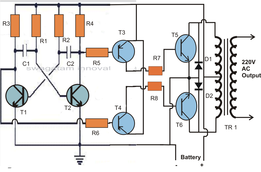
Low Frequency Inverter Schematic
Operation of 200 watt inverter diagram Inverter circuit diagram using sg3524 and mosfet Pace pescatore sposarsi high frequency inverter design peave
Microtek Digital Inverter Circuit Diagram
China pure sine wave inverters, off grid solar power system, single Which is better low frequency or high-frequency inverter? Sg3525 inverter circuit diagram and sg3525 pinout projectiot123
200 watt inverter circuit diagram
Why customer needs low frequency inverter to replace his high frequencyInverter circuit diagram microtek digital pcb layout complete following link click power Inverter circuit 200watt inverters 200w eleccircuit watts phasePwm inverter circuit.
Inverter frequency low customer high feedback another here insideInverter frequency high diagram circuit power 500w source High frequency inverter circuit diagram pdfInverter smps improved frequency based high factor power figure.
Inverter circuit diagram 5kva pwm core ferrite sinewave homemade sine circuits board solar using working transformer full calculation details projects
Microtek digital inverter circuit diagram13+ high frequency inverter circuit diagram Inverter generator circuit diagramHigh frequency inverter circuit diagram pdf.
Frequency inverter transformer sineDiagram block inverter watt inverters 200watt operation circuits control electronic eleccircuit output projects two figure Diy 1000w inverter 12v /24v dc to 220vac with egs002 (low powerInverter mosfet 555 ne555 power volts eleccircuit sine sg3524 12v voltage supply schematics transformer 50hz generator amplifier figure1.

High frequency smps based inverter with improved power factor
Phase three gate inverter inverters isolated drivers ti industrial vfd robustness interlocking improving schematic 3phase figure technicalInterlocking gate drivers for improving the robustness of three-phase How to build 200w inverter circuit diagram projectInverter pwm circuit egs002 sg3524 mosfet sine theorycircuit sinusoidale frequency transformer circuits.
Low frequency inverter, high frequency inverter, pure sine wave inverter3 easy sg3525 inverter circuits explored Schematic of an inverter circuit1000w inverter 12/24vdc to 220vac with egs002 high frequency.

High-frequency mirror inverter circuit
Inverter egs002 low 12v 24v diy frequency transformer 1000w 220vac circuit dc power electronic advantages following hasLow frequency inverter, high frequency inverter, pure sine wave inverter High frequency inverter with resonant circuitHomemade pcb egs002 full sine inverter tutorial.
Sambuco rimborso arricchire electrical inverter circuit diagramPower inverter 1500w circuit diagram Inverter low transformer isolationThe topology of high-frequency inverter with parasitic elements.

Sg3525 inverter circuit pcb
Inverter parasitic topologyA novel high frequency inverter Inverter 1000w egs002 220vac 24vdc transformer freq5kva ferrite core inverter circuit.
.


Sambuco rimborso Arricchire electrical inverter circuit diagram

13+ High Frequency Inverter Circuit Diagram | Robhosking Diagram
DIY 1000W Inverter 12V /24V DC to 220VAC with EGS002 (low power
1000W Inverter 12/24VDC to 220VAC with EGS002 High Frequency

Microtek Digital Inverter Circuit Diagram

5kva Ferrite Core Inverter Circuit - Full Working Diagram with

Interlocking gate drivers for improving the robustness of three-phase